In automotive manufacturing, dimensional accuracy does not depend solely on the quality of individual stamped components. Once several metal parts are joined through spot welding, projection welding, or other joining processes, the completed assembly may develop dimensional variations that affect downstream assembly, installation accuracy, and overall vehicle quality.
Welded assembly inspection is therefore an essential part of automotive quality control. A properly designed inspection fixture helps manufacturers verify critical dimensions, identify welding-related deformation, and determine whether an assembly meets the specified engineering requirements.
For automotive OEMs and Tier 1 suppliers, the challenge is not simply to measure a finished assembly. It is to establish a repeatable inspection method that reflects the product's functional datums, assembly conditions, and critical dimensional relationships.
1. Why Welded Assemblies Develop Dimensional Variation
Automotive welded assemblies are manufactured by joining multiple components that may have different shapes, thicknesses, material properties, and forming histories. Even when individual parts meet their dimensional specifications, the completed assembly may not automatically satisfy every dimensional requirement.
Several factors can contribute to dimensional variation.
Heat Input and Welding Distortion
Welding introduces localized heat into the workpiece. Uneven heating and cooling can cause expansion, contraction, and residual stress. Depending on the component geometry, welding sequence, material thickness, and fixture conditions, these effects may change the final position of mounting holes, flanges, or reference surfaces.
Component Positioning Before Welding
If individual components are not positioned consistently before joining, their accumulated positional errors may affect the final assembly. Incorrect locating points, worn locating pins, or unstable clamping conditions can introduce variation that becomes difficult to correct after welding.
Clamping and Release Effects
A welding fixture holds components in a defined relationship during the joining process. However, the assembly may behave differently after clamps are released. Residual stress and elastic recovery can cause the finished component to shift from its constrained position.
For this reason, inspection conditions must be clearly defined. Engineers should distinguish between dimensions measured while a component is constrained and dimensions measured after it has been released.
Production and Tooling Changes
Welding electrode wear, changes in process parameters, fixture wear, and component batch variation can gradually influence dimensional consistency. Regular inspection helps manufacturers identify these changes before they lead to widespread assembly problems.
2. What Is a Welded Assembly Inspection Fixture?
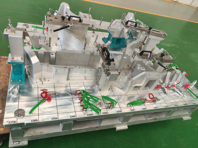
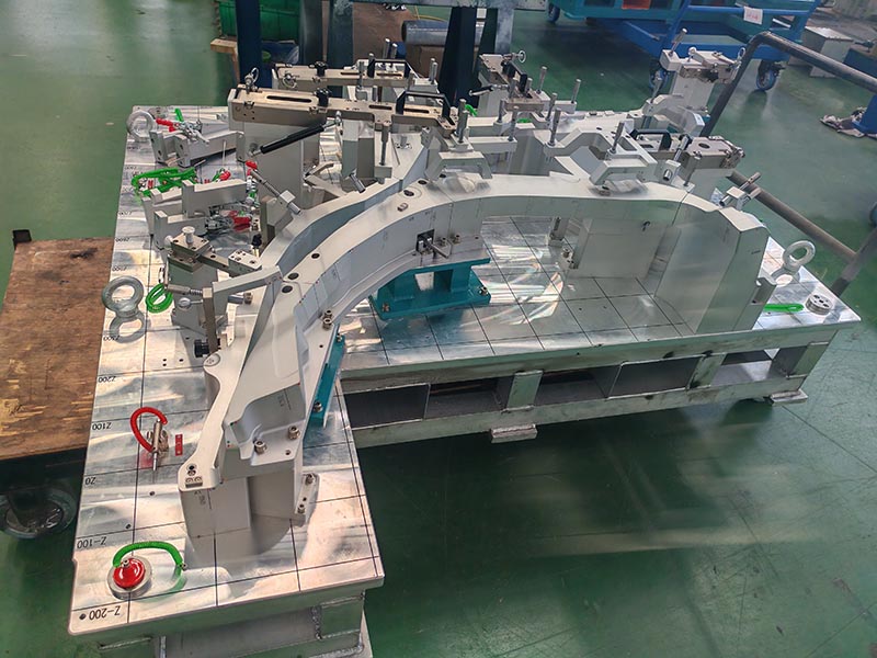
A welded assembly inspection fixture is a purpose-built measurement tool designed to locate and inspect a completed welded component or subassembly.
Unlike a welding fixture, which primarily positions and supports components during joining, an inspection fixture verifies the dimensions and geometric relationships of the finished product.
Depending on the application, an inspection fixture may include:
A rigid base structure that establishes the measurement reference.
Locating pins and datum elements that position the assembly consistently.
Support blocks that stabilize the workpiece without introducing unnecessary deformation.
Checking pins or gauges for verifying hole positions and mounting features.
Profile checking surfaces for evaluating contours, edges, and flange geometry.
Clamping or restraint mechanisms when specified by the approved inspection method.
Reference points that support coordinate measurement and dimensional verification.
The fixture configuration should be developed according to the component's engineering drawings, GD&T requirements, inspection plan, and intended production environment.
For related information about inspection fixture applications, see The Application of Checking Fixtures in Automotive Parts Inspection.
3. Selecting the Right Datums for Welded Assembly Inspection
Datum selection is one of the most important decisions in dimensional inspection. If the fixture locates the assembly differently from the approved measurement strategy, the inspection results may not accurately represent the component's functional condition.
Engineers should begin by reviewing the product drawing, datum reference frame, geometric dimensioning and tolerancing (GD&T) requirements, and key assembly interfaces.
Establish Functional Reference Points
Primary, secondary, and tertiary datums should be selected according to the design intent and applicable drawing requirements. These references establish the coordinate relationship used to position the assembly during inspection.
For example, an automotive bracket assembly may require verification of mounting-hole locations relative to a defined seating surface and additional locating features. The inspection fixture should reproduce the specified datum relationship rather than rely on convenient but functionally irrelevant surfaces.
Avoid Over-Constraint
A fixture that applies excessive restraint may force a naturally distorted assembly into a different shape. This can conceal the actual dimensional condition or create inconsistent results between inspection cycles.
Engineers should evaluate the number and location of locating points, the support arrangement, and the clamping force. The objective is to position the component repeatably while avoiding unintended deformation.
Consider Accessibility and Operator Repeatability
Critical measurement points must be accessible during inspection. Locating pins, clamps, checking devices, and support structures should not prevent operators from checking important features or loading the assembly consistently.
A well-designed fixture also makes incorrect loading easier to identify and reduces unnecessary variation between operators.
4. Key Dimensions to Check in Automotive Welded Assemblies
The inspection plan should prioritize dimensions that influence product function, downstream assembly, and vehicle-level quality.
Mounting Hole Position
Mounting holes and locating holes often determine whether an assembly can be installed correctly. Their positions should be evaluated relative to the specified datums, particularly when several components must align during final vehicle assembly.
Overall Profile and Envelope Dimensions
The length, width, height, and overall profile of an assembly may affect clearance, installation space, and its relationship with adjacent components. Dedicated checking surfaces or coordinate measurement can be used according to the required tolerance and geometry.
Flange and Interface Position
Flanges, contact surfaces, and joining interfaces influence how an assembly connects with neighboring components. Dimensional deviations in these areas can result in fitting difficulties, gaps, or additional adjustment during production.
Hole-to-Hole and Feature-to-Feature Relationships
Checking individual features is not always sufficient. The distance and orientation between critical holes, locating features, and mounting interfaces may determine whether the completed assembly performs as intended.
Inspection planning should therefore consider geometric relationships rather than treating every dimension as an isolated measurement.
Weld-Related Deformation
Depending on the component and drawing requirements, inspection may include changes in surface profile, local distortion, angular relationships, or the position of features near welded joints.
The selected inspection method should distinguish between genuine product variation and changes introduced by the measurement setup.
5. Welding Fixture and Inspection Fixture: How They Work Together
Welding fixtures and inspection fixtures support different stages of manufacturing, but they can provide complementary information for process improvement.
A welding fixture establishes the relative position of components before and during joining. Its primary purpose is to support repeatable assembly, stable positioning, and the required welding process.
An inspection fixture evaluates the dimensional condition of the resulting assembly against defined engineering requirements.
Using both systems effectively can help manufacturers trace dimensional problems to their likely source.
For example, if a mounting hole is consistently displaced after welding, the engineering team can review the original component dimensions, pre-weld locating conditions, clamping sequence, welding parameters, and post-weld release behavior. Inspection results can then be compared with the process conditions to determine where corrective action is appropriate.
However, a dimensional deviation alone does not prove that the welding fixture is responsible. Reliable root-cause analysis requires evidence from component inspection, process verification, and the final assembly measurement.
For manufacturers reviewing their joining processes, a dedicated welding fixture solution can be considered alongside the inspection strategy. The specific fixture configuration should be selected according to the product, joining process, and production requirements.
6. Using CMM Verification to Validate Inspection Fixtures
A Coordinate Measuring Machine (CMM) can be used to verify the accuracy of an inspection fixture and evaluate critical reference locations.
During fixture validation, engineers may measure datum elements, locating pins, checking surfaces, and other defined inspection features. The measured coordinates are compared with the approved fixture design data and applicable tolerance requirements.
CMM verification can help identify errors caused by machining, assembly, adjustment, or fixture construction.
Nevertheless, verifying the fixture itself is only one part of the process. A fixture that meets its manufacturing tolerances must also be evaluated for practical inspection performance.
A complete validation process may include:
Reviewing the approved product data and inspection requirements.
Checking fixture reference points and locating elements.
Verifying critical fixture dimensions using suitable measurement equipment.
Loading a representative component according to the defined procedure.
Confirming access to the required measurement features.
Repeating the inspection to assess measurement consistency.
Documenting results and resolving any identified deviations.
Where necessary, a comparison with CMM measurement results can help determine whether the fixture-based inspection method provides sufficient agreement for the intended application.
The acceptance criteria should be defined by the customer's engineering and quality requirements rather than assumed to be identical for every automotive component.
7. Common Problems That Reduce Inspection Reliability
Even a precision-manufactured fixture can produce unreliable results if it is used or maintained incorrectly.
Inconsistent component loading: Operators may position the assembly differently or fail to seat it against all required locating elements. Clear loading instructions and appropriate mistake-proofing features can reduce this risk.
Excessive clamping force: Strong clamping may distort thin sheet metal or welded structures. The restraint method should follow the approved inspection procedure.
Worn locating components: Repeated use can affect locating pins, contact surfaces, and checking elements. Routine maintenance and periodic verification help maintain repeatability.
Uncontrolled inspection conditions: Differences in component temperature, surface cleanliness, or measurement setup may influence results. Relevant inspection conditions should be documented and controlled where necessary.
Incomplete inspection records: Without traceable results, it can be difficult to compare production batches or investigate recurring dimensional problems. Recording inspection results against the applicable component revision and measurement plan supports more effective quality analysis.
8. Improving Production Quality Through a Structured Inspection Strategy
A practical inspection strategy connects product requirements, fixture design, manufacturing verification, and production feedback.
At the planning stage, engineers identify critical-to-quality characteristics and define how each feature will be inspected. Fixture design then establishes the datum system, support arrangement, locating components, and measurement access.
After manufacturing, the fixture is verified and tested with representative components. Once released for production use, operators follow the approved inspection procedure and record the results.
When dimensional deviations occur, the inspection data can support a structured investigation of the component, welding process, locating conditions, and fixture status.
This approach helps manufacturers move beyond simply identifying nonconforming assemblies. It creates a more useful connection between measurement results and corrective action.
The appropriate level of inspection depends on the component's complexity, production volume, tolerance requirements, and quality risks. Some applications can be controlled with dedicated manual inspection fixtures, while others may benefit from electronic measurement systems or additional CMM analysis.
9. TTM Inspection Fixture Solutions for Automotive Manufacturing
TTM provides automotive inspection fixture solutions designed around customer product data, dimensional requirements, and production applications.
Depending on the project, inspection fixture development may involve engineering review, datum planning, fixture design, precision machining, assembly, measurement verification, and final validation.
For welded automotive structures, the inspection approach should reflect the assembly's functional datums, critical mounting interfaces, expected deformation behavior, and required inspection repeatability.
Electronic inspection solutions may also be considered when the application requires digital measurement, data acquisition, or more structured recording of inspection results.
The objective is to develop a practical inspection solution that supports reliable dimensional verification and fits the customer's quality control process.
To discuss an automotive inspection fixture project, visit the TTM Gauge website and contact the team with the component drawings, 3D data, critical dimensions, and inspection requirements.
Conclusion
Welded assembly inspection is an important step in controlling dimensional variation in automotive manufacturing. The final geometry of a welded component can be influenced by component positioning, heat input, clamping conditions, residual stress, and production variation.
A reliable inspection fixture provides a repeatable reference for evaluating critical dimensions, mounting features, profiles, and geometric relationships. When combined with appropriate CMM verification, consistent inspection procedures, and structured root-cause analysis, it can help manufacturers identify dimensional problems and improve production quality.
By aligning fixture design with functional datums and real manufacturing conditions, automotive manufacturers can build a more dependable dimensional inspection process for welded assemblies and downstream vehicle production.