In automotive manufacturing, an inspection fixture must do more than hold a component in a fixed position. It must provide reliable and repeatable measurement conditions so that quality engineers can determine whether a part meets its dimensional requirements.
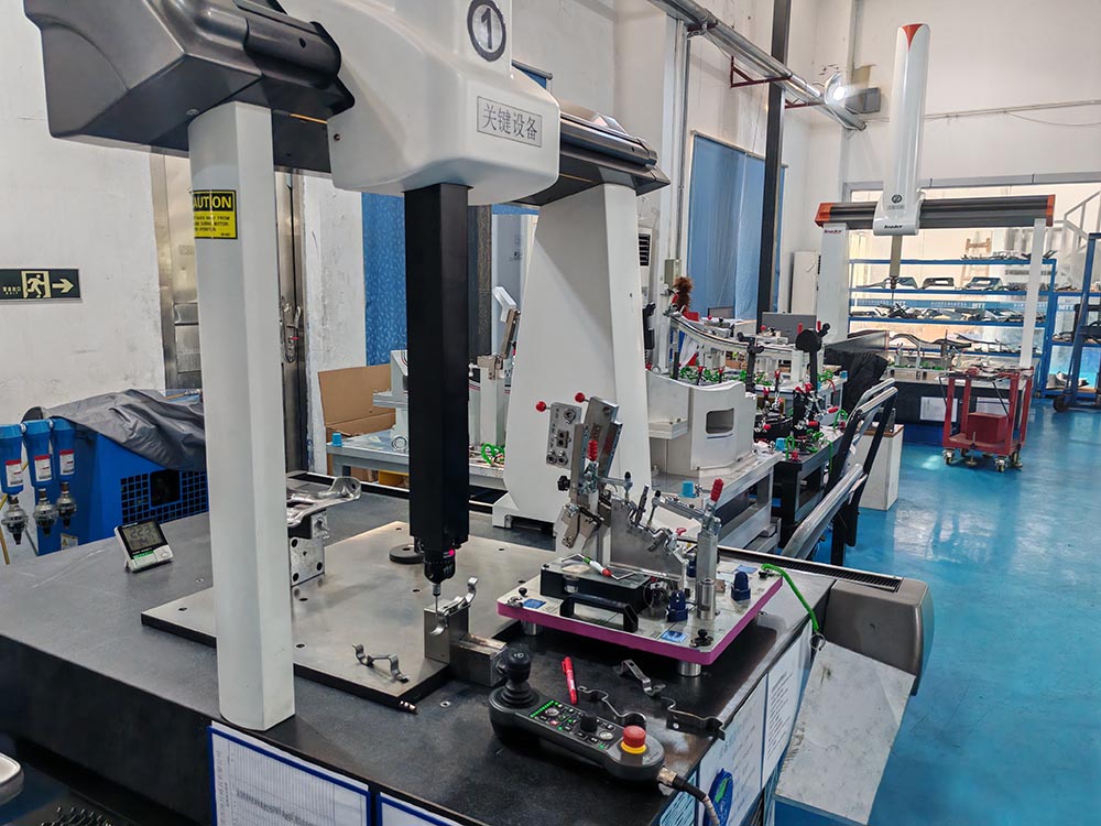
Even a well-designed automotive inspection fixture may produce unreliable results if its locating elements, checking devices, measurement procedures, or reference conditions have not been properly verified.
This is why inspection fixture validation is an essential stage before a new fixture is released for production use.
For automotive OEMs and Tier 1 suppliers, a structured validation process helps confirm that the fixture performs as intended, produces consistent inspection results, and supports the approved dimensional inspection requirements.
This article explains the key steps involved in automotive inspection fixture validation, including repeatability testing, measurement correlation, calibration, and production approval.
1. Why Automotive Inspection Fixture Validation Matters
An automotive checking fixture establishes a controlled reference condition for inspecting components such as stamped sheet metal parts, welded assemblies, plastic components, and Body-in-White structures.
However, several factors can influence the reliability of inspection results:
Locating pin position and dimensional accuracy.
Fixture base stability and structural rigidity.
Contact conditions between the component and locating elements.
Clamping force and potential component deformation.
Wear of checking pins, locating blocks, and inspection surfaces.
Measurement device accuracy and calibration status.
Differences in operator loading and inspection procedures.
If these factors are not evaluated before production release, a fixture may produce inconsistent results even when the inspected component has not changed.
Proper validation helps identify these issues before they affect production quality decisions.
2. Verify the Fixture Against Approved Engineering Data
The first step is to confirm that the manufactured inspection fixture matches the approved engineering design.
The validation team should review the latest released product data, fixture drawings, inspection plans, and relevant GD&T requirements.
Important verification items include:
Primary, secondary, and tertiary datum locations.
Locating pin coordinates and diameters.
Checking surface and profile positions.
Reference hole and mounting point locations.
Support block and clamping mechanism positions.
Overall fixture dimensions and structural alignment.
Identification of critical inspection characteristics.
CMM measurement can be used to verify important fixture reference locations and manufactured features against the approved CAD model or fixture drawing.
For complex fixtures, the inspection report should clearly identify the measured features, nominal values, actual values, and deviations.
It is also important to confirm that the fixture is built according to the correct product revision. Using outdated CAD data may lead to incorrect inspection results even when the fixture itself is manufactured accurately.
3. Perform Repeatability Testing
Repeatability is one of the most important performance indicators for an automotive inspection fixture.
It describes whether the same measurement result can be obtained when the same part is inspected repeatedly under the same conditions.
A practical repeatability test can follow this process:
Step 1: Select a representative component
Choose a component that represents the actual production geometry and includes important inspection characteristics.
Step 2: Establish the standard loading procedure
Position the component according to the defined locating sequence, ensuring that all datum contacts are correctly established.
Step 3: Perform the first inspection
Record the measurements of critical holes, profiles, mounting points, and other specified characteristics.
Step 4: Remove and reload the component
Unload the part completely and repeat the positioning and inspection procedure.
Step 5: Repeat the measurement cycle
Perform multiple loading and measurement cycles under controlled conditions.
Step 6: Compare the results
Analyze the measurement variation to determine whether the fixture provides sufficiently consistent positioning and measurement conditions.
The number of cycles, operators, and acceptance criteria should be defined in the project validation plan.
If significant differences appear between repeated measurements, engineers should investigate locating contact, clamp force, component deformation, checking device clearance, and operator handling.
4. Evaluate Measurement Reproducibility and Gauge R&R
Repeatability alone does not demonstrate that an inspection process is fully reliable.
Reproducibility considers whether different operators can obtain consistent results when following the same inspection procedure.
For this reason, automotive manufacturers may use Measurement System Analysis (MSA), including Gauge Repeatability and Reproducibility (Gauge R&R), to evaluate measurement system variation.
A typical Gauge R&R study considers:
Variation between repeated measurements by the same operator.
Variation between different operators.
Differences between inspected parts.
Total measurement variation relative to the manufacturing tolerance.
For electronic inspection fixtures, the study may also consider sensor stability, signal acquisition, software configuration, and measurement channel consistency.
It is important to distinguish fixture validation from a complete Gauge R&R study. Fixture geometry verification, measurement device calibration, and measurement system analysis address different aspects of inspection reliability.
They should be combined when required by the customer's quality plan rather than treated as interchangeable activities.
5. Conduct CMM Correlation and Dimensional Verification
CMM correlation is another important step in validating an automotive inspection fixture.
The purpose is to compare measurements obtained using the inspection fixture with results from an appropriate reference measurement method, such as a Coordinate Measuring Machine (CMM).
A typical correlation process includes:
Select a representative part with clearly defined inspection characteristics.
Establish consistent datum references for both measurement methods.
Measure the selected characteristics using the inspection fixture.
Measure the corresponding characteristics using the CMM.
Compare the results and calculate the differences.
Investigate deviations that exceed the agreed acceptance criteria.
The comparison should use equivalent measurement definitions, reference conditions, and component states.
For example, hole position, profile deviation, mounting surface location, and critical dimensional relationships may be selected according to the component's inspection plan.
A correlation report provides useful evidence that the inspection fixture can produce results consistent with the reference measurement method within the specified requirements.
However, differences between measurement methods should not automatically be attributed to fixture accuracy. Datum alignment, probe strategy, measurement uncertainty, and part deformation must also be considered.
6. Check Locating, Clamping and Component Deformation
A fixture may be manufactured accurately but still generate unreliable results if it changes the geometry of the component during loading.
This is particularly important for thin sheet metal parts, large automotive panels, and components with complex formed surfaces.
During validation, engineers should check:
Locating condition
All locating points should establish the intended reference condition without creating unnecessary constraint or interference.
Clamping force
Clamps should secure the component without introducing unacceptable deformation.
Contact condition
The component should make the required contact with datum elements and support surfaces.
Unclamping behavior
The component should not experience unexpected displacement or permanent deformation after release.
Operator accessibility
Locating and clamping operations should be practical and repeatable during normal production inspection.
For more complex assemblies, the inspection method should also distinguish between constrained and released measurement conditions where these produce different dimensional results.
7. Verify Electronic Measurement Systems
Electronic inspection fixtures introduce additional validation requirements because they combine mechanical positioning with sensors, electrical connections, and measurement software.
The validation process should include:
Sensor installation and mounting position verification.
Measurement range and resolution checks.
Zero-point and reference value verification.
Signal stability and channel assignment checks.
Cable routing and electrical connection inspection.
Software configuration and measurement unit verification.
Data recording and output consistency checks.
Where electronic sensors are used to measure contours, displacement, or dimensional variation, the system should be checked using suitable reference standards or approved master conditions.
Electronic measurement systems should also have clearly defined calibration and maintenance requirements.
For applications involving multiple measurement channels, engineers should confirm that each channel corresponds to the correct inspection feature.
This helps prevent incorrect data assignment and improves the reliability of digital inspection results.
8. Establish Fixture Calibration and Maintenance Requirements
Inspection fixture performance can change over time because of repeated operation, mechanical wear, accidental impact, environmental conditions, or component modifications.
Therefore, validation should not be considered a one-time activity.
A practical calibration and maintenance plan should define:
Inspection frequency for critical locating and checking elements.
Verification methods for checking pins and reference surfaces.
Calibration requirements for electronic sensors.
Procedures for identifying damaged or worn components.
Records of fixture modifications and repairs.
Revalidation requirements after significant changes.
The calibration interval should be based on fixture usage, measurement risk, historical performance, customer requirements, and the manufacturer's quality procedures.
Any modification to datum elements, checking devices, or measurement software should be reviewed to determine whether partial or complete revalidation is necessary.
9. Prepare the Final Inspection Fixture Validation Report
Before a new automotive inspection fixture is released for production use, its validation results should be documented.
A complete validation report may include:
Fixture identification and project information.
Approved CAD and drawing revision.
CMM dimensional verification results.
Repeatability test records.
Gauge R&R results, where applicable.
CMM correlation results.
Electronic measurement verification records.
Identified deviations and corrective actions.
Calibration and maintenance requirements.
Final approval status.
The acceptance criteria should be established before testing and agreed upon by the relevant engineering and quality teams.
If a fixture does not meet the required criteria, corrective actions should be completed and the affected validation activities repeated before production approval.
This documentation provides traceability and helps maintain consistent inspection conditions throughout the product lifecycle.
10. TTM Automotive Inspection Fixture Engineering Solutions
TTM provides customized automotive inspection fixture solutions for different component geometries and dimensional inspection requirements.
Our product and engineering capabilities cover:
Electronic checking fixtures.
Single and assembly sheet metal checking fixtures.
Plastic component inspection fixtures.
Carbon fiber inspection fixtures.
Body-in-White checking fixtures.
CMM holding fixtures.
Cubing checking fixtures.
Welding fixtures and related tooling solutions.
Depending on project requirements, fixture development can include engineering review, datum planning, fixture design, precision machining, assembly, CMM verification, and inspection validation.
By considering measurement accessibility, repeatability, structural stability, and production operating conditions during fixture development, TTM aims to provide practical inspection solutions for automotive manufacturers and Tier 1 suppliers.
Explore our Electronic Checking Fixture Solutions and Sheet Metal Checking Fixtures for more information.
For broader automotive manufacturing capabilities, visit TTM GROUP.
Conclusion
Automotive inspection fixture validation is essential for ensuring that a newly manufactured fixture can support reliable dimensional inspection in production.
A structured validation process should cover engineering data verification, repeatability testing, measurement reproducibility, CMM correlation, mechanical inspection, electronic system verification, and calibration planning.
More importantly, fixture validation should focus not only on whether the fixture meets its design specifications, but also on whether it provides consistent and practical inspection conditions during actual production use.
For automotive OEMs and Tier 1 suppliers, a properly validated inspection fixture helps establish confidence in dimensional measurement, improve quality control, and support stable manufacturing operations.