In automotive manufacturing, a component may contain dozens of critical features that must be verified before assembly. These features can include mounting holes, formed edges, locating surfaces, profile sections, and interfaces between adjoining components. When several characteristics need to be inspected within one fixture, the engineering challenge extends beyond simply adding more measurement points.
A well-designed multi-point automotive inspection fixture must provide consistent part positioning, accessible measurement locations, a practical inspection sequence, and reliable data collection. If these elements are not coordinated during the engineering stage, operators may encounter difficult probe access, inconsistent readings, or unnecessary inspection delays.
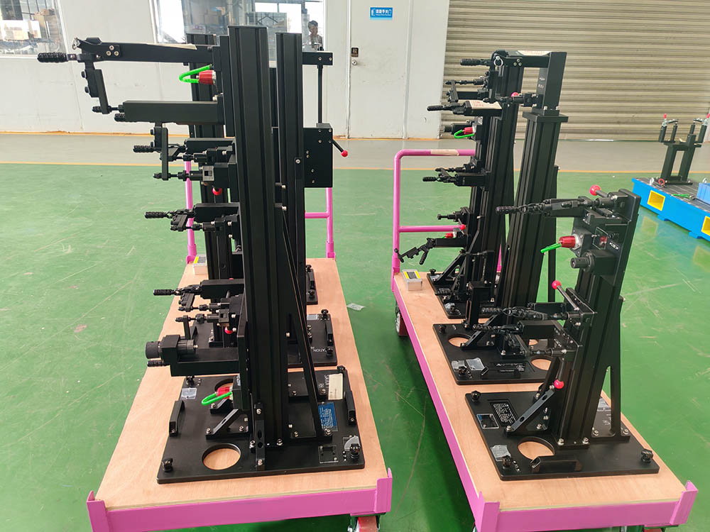
This article examines several engineering considerations that help make multi-point inspection fixtures more practical for automotive production environments.
1. Start with Inspection Characteristics, Not the Number of Measuring Points
The first step in multi-point inspection fixture design is to classify the characteristics that need to be measured.
Different features require different inspection methods. A mounting hole may need a checking pin or an electronic displacement sensor, while a formed flange may require a profile checking device. A curved surface may need several measurement locations to evaluate its shape accurately.
Rather than distributing inspection points evenly across the component, engineers should identify which characteristics are functionally important and how each one relates to the approved product drawing.
A useful inspection plan should distinguish between:
Critical assembly features that influence component fit.
Hole positions and diameters that require dimensional verification.
Surface profiles and formed edges that affect contour accuracy.
Reference points used to establish measurement relationships.
Features that require additional monitoring because of manufacturing variation.
This classification helps prevent unnecessary inspection complexity. It also ensures that every measuring device has a defined purpose within the overall quality control process.
2. Establish a Stable Reference System for Every Inspection Cycle
Measurement results are only meaningful when the component is positioned consistently.
For automotive sheet metal parts, the locating strategy should follow the approved datum structure and relevant geometric dimensioning and tolerancing requirements. Primary locating surfaces, secondary locators, supporting elements, and locating pins must work together to establish a repeatable reference position.
The engineering team should also consider the flexibility of the component itself. Thin panels and formed sheet metal parts can deform under excessive clamping force. A fixture may therefore position a component correctly while still producing misleading readings if the clamping arrangement changes its shape.
To reduce this risk, the design should consider:
The stiffness of the component around each locating point.
The relationship between locating points and inspection features.
The direction and magnitude of clamping forces.
The sequence in which supports and clamps engage.
The ease of loading and unloading the component without disturbing its reference position.
The objective is to reproduce the intended inspection condition without introducing unnecessary deformation.
For projects involving several related components or assembly interfaces, engineers can also review TTM's Assembly Sheet Metal Checking Fixtures for a relevant fixture category.
3. Plan Probe Access and Inspection Sequence Together
A common design problem occurs when measurement devices are positioned independently without considering how an operator or probe will reach each feature.
A sensor may fit into the fixture model but become difficult to access after the component is loaded. Clamps, support blocks, cables, and neighboring measurement devices can obstruct the inspection path. Some points may be measurable only after a clamp is released or a mechanism is repositioned.
These issues are easier to resolve during digital fixture design than after manufacturing.
Engineers should review the complete measurement path, including:
Probe approach direction and available clearance.
Interference between sensors, clamps, and the component.
Cable routing and protection for electronic systems.
Access for calibration, adjustment, and maintenance.
The order in which measurement points can be checked safely.
An efficient inspection sequence should minimize unnecessary repositioning while maintaining the correct datum condition. Where different operations require different clamping states, the sequence must clearly define when each state is established and which measurements remain valid.
For complex parts, a digital review of the complete fixture assembly can help identify interference before components enter production.
4. Select the Right Measurement Method for Each Feature
Not every characteristic needs to be measured using the same technology.
Mechanical checking elements can be effective for rapid go/no-go verification and routine production checks. Electronic measurement devices can provide numerical readings for characteristics that require closer monitoring or digital recording. Coordinate measuring machines (CMMs) can support detailed dimensional verification during fixture validation and engineering analysis.
The appropriate method depends on the tolerance requirement, inspection frequency, production environment, and required output data.
Mechanical checking elements
Checking pins, profile gauges, and dedicated contact elements are useful when operators need a straightforward method to verify specific characteristics. Their effectiveness depends on correct manufacturing, calibration, maintenance, and operating procedures.
Electronic measurement systems
Electronic sensors can collect measurement values from multiple locations and transmit them to a data acquisition system. When correctly configured and validated, these systems can reduce manual recording work and make it easier to review measurement history.
TTM provides Electronic Checking Fixture solutions for applications where electronic measurement is required.
CMM verification
A CMM can be used to verify fixture reference points, locating features, and critical inspection elements against approved engineering data. It is particularly useful during fixture acceptance and when investigating discrepancies between fixture readings and other measurement methods.
These methods are complementary rather than interchangeable. A practical inspection strategy selects the method that fits each characteristic and the intended production use.
5. Control Measurement Errors Before Collecting More Data
Increasing the number of inspection points does not automatically improve measurement quality. If the locating system is unstable or a sensor is incorrectly calibrated, additional measurements may simply produce more inconsistent data.
Multi-point fixture development should therefore include a clear verification plan.
Important checks include:
Fixture geometry verification: Confirm that critical locating elements and measurement references conform to the approved design.
Sensor calibration: Verify that electronic measurement devices operate within their specified measurement range and accuracy requirements.
Repeatability checks: Measure the same component repeatedly under controlled conditions to determine whether the fixture and measurement process produce consistent results.
Loading consistency: Confirm that different operators can position and clamp the component according to the defined work instructions.
Correlation checks: Where appropriate, compare fixture results with an approved reference measurement method to investigate significant differences.
It is also important to distinguish fixture accuracy from the overall measurement process. Sensor performance, component temperature, part-to-part variation, operator technique, and environmental conditions can all influence the final result.
A structured validation process helps identify these influences before the fixture is released for routine inspection.
6. Make Inspection Data Traceable and Useful
For production quality teams, the value of a multi-point inspection fixture depends not only on the readings it produces but also on how those readings are recorded and interpreted.
A useful data record should identify the inspected characteristic, its applicable specification, the measured value where applicable, and the inspection result. Depending on the production system, additional information may include the part identification, inspection time, equipment identification, and relevant calibration status.
For electronic fixtures, engineers should confirm that the measurement software maps each sensor to the correct inspection characteristic. Sensor identifiers, engineering feature names, measurement units, acceptance limits, and data output fields should be checked before production use.
Data collection should also support practical troubleshooting. When a critical dimension begins to drift, quality personnel need to identify which feature changed and determine whether the cause may relate to the forming process, component positioning, fixture condition, or measurement system.
Inspection data can support process monitoring, but it should not be treated as proof of a manufacturing problem without reviewing measurement uncertainty and the relevant production conditions.
7. Design for Maintenance and Long-Term Stability
A fixture that performs well during initial acceptance must also remain practical throughout its service life.
Locating pins, checking elements, clamps, sensors, and moving mechanisms may experience wear or require adjustment. If these components are difficult to reach, maintenance can become time-consuming and may introduce new alignment errors.
A maintenance-conscious design should provide adequate access to replaceable elements, protect sensitive components from impact, and allow critical references to be checked during scheduled verification.
For electronic systems, connectors and cables should be routed to reduce accidental damage. Sensor replacement procedures should also define whether recalibration or renewed dimensional verification is required.
Clear identification of replaceable components and documented maintenance records help quality teams maintain consistent inspection conditions over time.
8. An Engineering Review Checklist Before Fixture Release
Before a multi-point automotive inspection fixture enters production, the project team should review the following items:
All required inspection characteristics are identified and linked to the approved product data.
The locating strategy reflects the specified datum references.
Clamping does not introduce unacceptable component deformation.
Measurement devices can reach their assigned features without interference.
The inspection sequence is clear and practical for operators.
Critical fixture dimensions and reference locations have been verified.
Electronic channels, units, and feature assignments are checked where applicable.
Repeatability and relevant correlation checks have been completed.
Operating instructions, maintenance requirements, and data records are available.
This review helps identify issues that may otherwise appear only after the fixture reaches the production line.
TTM Group: Automotive Inspection Fixture Engineering
TTM Group provides automotive fixture and tooling solutions for manufacturers that require dependable dimensional inspection and production quality control.
Depending on the component and application, inspection fixture projects may involve sheet metal parts, body structures, electronic measurement systems, and dedicated dimensional verification equipment. Fixture development should always be based on the customer's product data, inspection requirements, tolerance specifications, and production conditions.
By coordinating locating strategy, measurement access, verification procedures, and maintenance requirements during the design stage, manufacturers can develop inspection fixtures that are easier to operate and better suited to long-term production use.
To learn more about TTM's capabilities, visit the TTM Group company profile or explore its automotive inspection fixture solutions.
Conclusion
Designing a multi-point automotive inspection fixture requires more than accommodating a large number of measuring devices. The fixture must establish a stable reference system, provide practical measurement access, control potential sources of error, and support consistent data recording.
When these requirements are addressed together, the resulting inspection process becomes easier to validate, operate, and maintain.
For automotive manufacturers, a carefully engineered inspection fixture is an important part of a reliable dimensional quality control system, helping connect engineering requirements with everyday production inspection.